
R301 General
R301.1 Scope
The technical requirements in Chapter 3 shall apply where required by Chapter 2 or where referenced by a requirement in this document.
R302 Pedestrian Access Routes
R302.1 General
Pedestrian access routes shall comply with R302.
R302.2 Components
Pedestrian access routes shall consist of one or more of the following components:
- Sidewalks and other pedestrian circulation paths, or a portion of sidewalks and other pedestrian circulation paths, complying with R302.3 through R302.7;
- Pedestrian street crossings and at-grade rail crossings complying with R302.3 through R302.7, and R306;
- Pedestrian overpasses and underpasses and similar structures complying with R302.3 through R302.7;
- Curb ramps and blended transitions complying with R302.7 and R304;
- Ramps complying with R407;
- Elevators and limited use/limited application elevators complying with sections 407 or 408 of Appendix D to 36 CFR part 1191;
- Platform lifts complying with section 410 of Appendix D to 36 CFR part 1191; and
- Doors, doorways, and gates complying with section 404 of Appendix D to 36 CFR part 1191.
Advisory R302.2 Components. The technical requirement for elevators, limited use/limited application elevators, platform lifts, and doors, doorways, and gates are contained in the Americans with Disabilities Act Accessibility Guidelines for Buildings and Facilities and the Architectural Barriers Act Accessibility Guidelines (36 CFR part 1191).
R302.3 Continuous Width
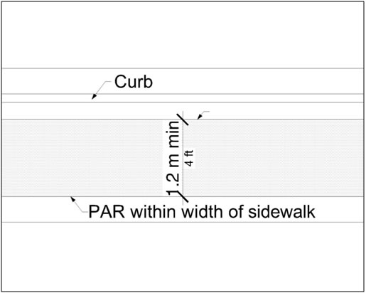
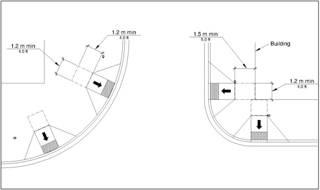
Except as provided in R302.3.1 and R302.3.2, the continuous clear width of pedestrian access routes shall be 1.2 m (4.0 ft) minimum, exclusive of the width of the curb.
Advisory R302.3 Continuous Width. The continuous clear width requirements in R302.3 apply to sidewalks and other pedestrian circulation paths, pedestrian street crossings and at-grade rail crossings, and pedestrian overpasses and underpasses and similar structures (see R302.2). Clear width requirements are contained in R304.5.1 for curb ramps and blended transitions, and in R407.4 for ramps. Where sidewalks are wider than 1.2 m (4.0 ft), only a portion of the sidewalk is required to comply with the requirements in R302.3 through R302.7. Additional maneuvering space should be provided at turns or changes in direction, transit stops, recesses and alcoves, building entrances, and along curved or angled routes, particularly where the grade exceeds 5 percent. R210 prohibits street furniture and other objects from reducing the minimum clear width of pedestrian access routes.
R302.3.1 Medians and Pedestrian Refuge Islands
The clear width of pedestrian access routes within medians and pedestrian refuge islands shall be 1.5 m (5.0 ft) minimum.
R302.3.2 Shared Use Paths
A pedestrian access route shall be provided for the full width of a shared use path.
R302.4 Passing Spaces
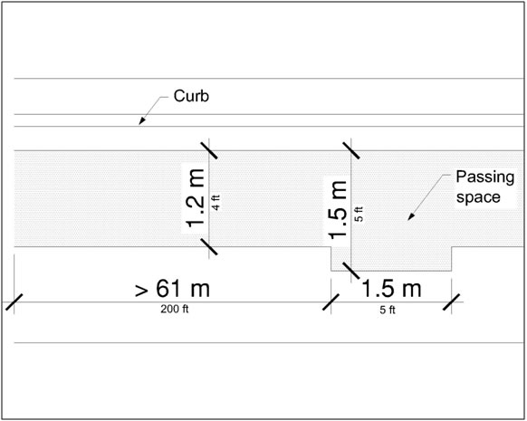
Where the clear width of pedestrian access routes is less than 1.5 m (5.0 ft), passing spaces shall be provided at intervals of 61 m (200.0 ft) maximum. Passing spaces shall be 1.5 m (5.0 ft) minimum by 1.5 m (5.0 ft) minimum. Passing spaces are permitted to overlap pedestrian access routes.
R302.5 Grade
The grade of pedestrian access routes shall comply with R302.5.
Advisory R302.5 Grade. The grade requirements in R302.5 apply to sidewalks and other pedestrian circulation paths, pedestrian street crossings and at-grade rail crossings, and pedestrian overpasses and underpasses and similar structures (see R302.2). The grade of the pedestrian access route is measured parallel to the direction of pedestrian travel. Running slope requirements are contained in R304.2.2 for perpendicular curb ramps, in R304.3.2 for parallel curb ramps, in R304.4.1 for blended transitions, and in R407.2 for ramps.
R302.5.1 Within Street or Highway Right-of-Way
Except as provided in R302.5.3, where pedestrian access routes are contained within a street or highway right-of-way, the grade of pedestrian access routes shall not exceed the general grade established for the adjacent street or highway.
R302.5.2 Not Within Street or Highway Right-of-Way
Where pedestrian access routes are not contained within a street or highway right-of-way, the grade of pedestrian access routes shall be 5 percent maximum.
R302.5.3 Within Pedestrian Street Crossings
Where pedestrian access routes are contained within a pedestrian street crossing, the grade of pedestrian access routes shall be 5 percent maximum.
R302.5.4 Physical Constraints
Where compliance with R302.5.1 or R302.5.2 is not practicable due to existing terrain or infrastructure, right-of-way availability, a notable natural feature, or similar existing physical constraints, compliance is required to the extent practicable.
R302.5.5 Regulatory Constraints
Where compliance with R302.5.1 or R302.5.2 is precluded by federal, state, or local laws the purpose of which is to preserve threatened or endangered species; the environment; or archaeological, cultural, historical, or significant natural features, compliance is required to the extent practicable.
R302.6 Cross Slope
Except as provided in R302.6.1 and R302.6.2, the cross slope of pedestrian access routes shall be 2 percent maximum.
Advisory R302.6 Cross Slope. The cross slope requirements in R302.6 apply to sidewalks and other pedestrian circulation paths, pedestrian street crossings and at-grade rail crossings, and pedestrian overpasses and underpasses and similar structures (see R302.2). The cross slope of the pedestrian access route is measured perpendicular to the direction of pedestrian travel. Cross slope requirements are contained in R304.5.3 for curb ramps and blended transitions, and in R407.3 for ramps.
R302.6.1 Pedestrian Street Crossings Without Yield or Stop Control
Where pedestrian access routes are contained within pedestrian street crossings without yield or stop control, the cross slope of the pedestrian access route shall be 5 percent maximum.
Advisory R302.6.1 Pedestrian Street Crossings Without Yield or Stop Control. Pedestrian street crossings without yield or stop control are crossings where there is no yield or stop sign, or where there is a traffic signal that is designed for the green phase. At pedestrian street crossings without yield or stop control, vehicles can proceed through the intersection without slowing or stopping. Where pedestrian access routes are contained within pedestrian street crossings with yield or stop control, the cross slope of the pedestrian access route must be 2 percent maximum (see R302.6). At pedestrian street crossings with yield or stop control, vehicles slow or stop before proceeding through the intersection.
R302.6.2 Midblock Pedestrian Street Crossings
Where pedestrian access routes are contained within midblock pedestrian street crossings, the cross slope of the pedestrian access route shall be permitted to equal the street or highway grade.
R302.7 Surfaces
The surfaces of pedestrian access routes and elements and spaces required to comply with R302.7 that connect to pedestrian access routes shall be firm, stable, and slip resistant and shall comply with R302.7.
Advisory R302.7 Surfaces. The surface requirements in R302.7 apply to sidewalks and other pedestrian circulation paths, pedestrian street crossings and at-grade rail crossings, pedestrian overpasses and underpasses and similar structures, and curb ramps and blended transitions (see R302.2). The surface requirements in R302.7 also apply to surfaces at the following accessible elements and spaces that connect to pedestrian access routes:
- Clear spaces (see R404.2), including clear spaces at operable parts (see R403.2) such as accessible pedestrian signals and pedestrian pushbuttons (see R209), clear spaces at street furniture such as benches (see R212.6), and clear spaces within transit shelters (see R308.2);
- Boarding and alighting areas and boarding platforms at transit stops (see R308.1.3.1);
- Access aisles at accessible parking spaces (see R309.2.1 and R309.3) and accessible passenger loading zones (see R310.3.4); and
- Ramp runs and landings (see R407.7).
R302.7.1 Vertical Alignment
Vertical alignment shall be generally planar within pedestrian access routes (including curb ramp runs, blended transitions, turning spaces, and gutter areas within pedestrian access routes) and surfaces at other elements and spaces required to comply with R302.7 that connect to pedestrian access routes. Grade breaks shall be flush. Where pedestrian access routes cross rails at grade, the pedestrian access route surface shall be level and flush with the top of rail at the outer edges of the rails, and the surface between the rails shall be aligned with the top of rail.
Advisory R302.7.1 Vertical Alignment. Pedestrian access route surfaces must be generally planar and smooth. Surfaces should be chosen for easy rollability. Surfaces that are heavily textured, rough, or chamfered and paving systems consisting of individual units that cannot be laid in plane will greatly increase rolling resistance and subject pedestrians who use wheelchairs, scooters, and rolling walkers to the stressful and often painful effects of vibration. Such materials should be reserved for borders and decorative accents located outside of or only occasionally crossing the pedestrian access route. Surfaces should be designed, constructed, and maintained according to appropriate industry standards, specifications, and recommendations for best practice.
R302.7.2 Vertical Surface Discontinuities
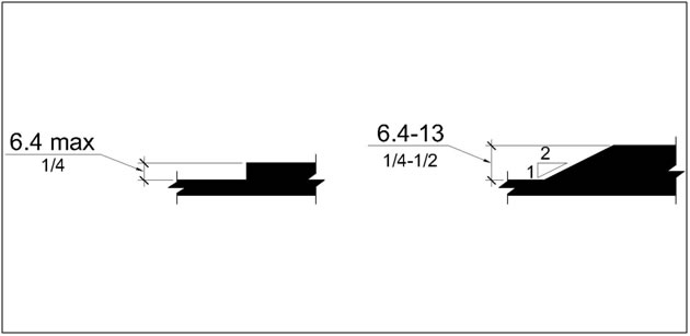
Vertical surface discontinuities shall be 13 mm (0.5 in) maximum. Vertical surface discontinuities between 6.4 mm (0.25 in) and 13 mm (0.5 in) shall be beveled with a slope not steeper than 50 percent. The bevel shall be applied across the entire vertical surface discontinuity.
Advisory R302.7.2 Vertical Surface Discontinuities. The allowance for vertical surface discontinuities is for occasional expansion joints and objects such as utility covers, vault frames, and gratings that cannot be located in another portion of the sidewalk outside the pedestrian access route. However, objects such as utility covers, vault frames, and gratings should not be located on curb ramp runs, blended transitions, turning spaces, or gutter areas within the pedestrian access route. This may not always be possible in alterations, but should be avoided wherever possible. Vertical surface discontinuities between unit pavers should be minimized.
R302.7.3 Horizontal Openings
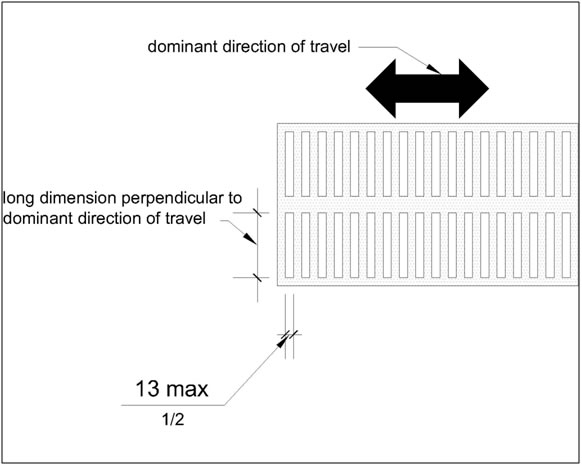
Horizontal openings in gratings and joints shall not permit passage of a sphere more than 13 mm (0.5 in) in diameter. Elongated openings in gratings shall be placed so that the long dimension is perpendicular to the dominant direction of travel.
R302.7.4 Flangeway Gaps
Flangeway gaps at pedestrian at-grade rail crossings shall be 64 mm (2.5 in) maximum on non-freight rail track and 75 mm (3 in) maximum on freight rail track.
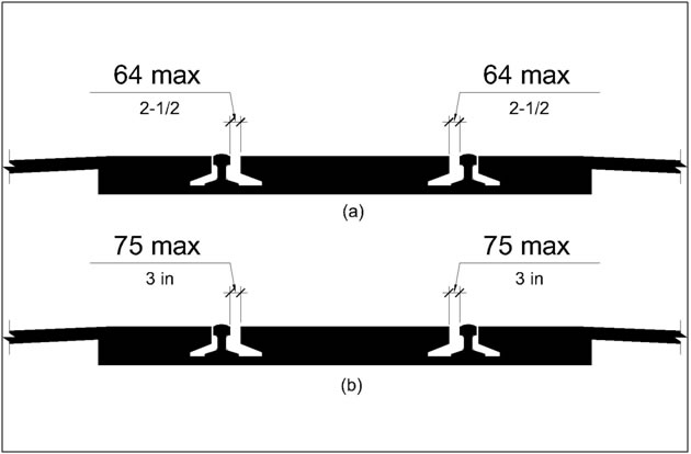
Advisory R302.7.4 Flangeway Gaps. Flangeway gaps are necessary to allow the passage of train wheel flanges. Flangeway gaps pose a potential hazard to pedestrians who use wheelchairs because the gaps can entrap the wheelchair casters.
R303 Alternate Pedestrian Access Routes
(See R205)
R304 Curb Ramps and Blended Transitions
R304.1 General
Curb ramps and blended transitions shall comply with R304.
Advisory R304.1 General. There are two types of curb ramps:
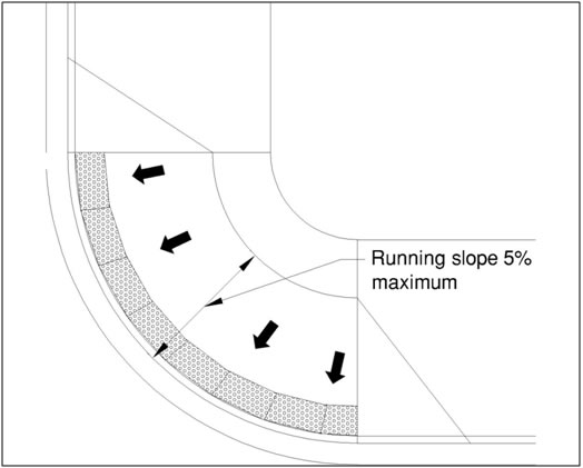
- Perpendicular curb ramps have a running slope that cuts through or is built up to the curb at right angles or meets the gutter break at right angles where the curb is curved. On large corner radiuses, it will be necessary to indent the gutter break on one side of the curb ramp in order for the curb ramp to meet the gutter break at right angles.
- Parallel curb ramps have a running slope that is in-line with the direction of sidewalk travel and lower the sidewalk to a level turning space where a turn is made to enter the pedestrian street crossing.
Perpendicular curb ramps can be provided where the sidewalk is at least 3.7 m (12.0 ft) wide. Parallel curb ramps can be provided where the sidewalk is at least 1.2 m (4.0 ft) wide. Parallel and perpendicular curb ramps can be combined. A parallel curb ramp is used to lower the sidewalk to a mid-landing and a short perpendicular curb ramp connects the landing to the street. Combination curb ramps can be provided where the sidewalk is at least 1.8 m (6.0 ft) wide.
Blended transitions are raised pedestrian street crossings, depressed corners, or similar connections between pedestrian access routes at the level of the sidewalk and the level of the pedestrian street crossing that have a grade of 5 percent or less. Blended transitions are suitable for a range of sidewalk conditions.
R304.2 Perpendicular Curb Ramps
Perpendicular curb ramps shall comply with R304.2 and R304.5.
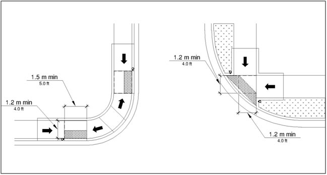
R304.2.1 Turning Space
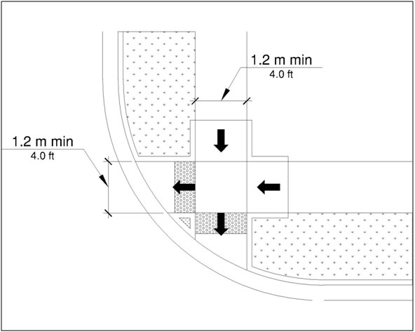
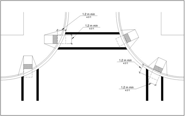
A turning space 1.2 m (4.0 ft) minimum by 1.2 m (4.0 ft) minimum shall be provided at the top of the curb ramp and shall be permitted to overlap other turning spaces and clear spaces. Where the turning space is constrained at the back-of-sidewalk, the turning space shall be 1.2 m (4.0 ft) minimum by 1.5 m (5.0 ft) minimum. The 1.5 m (5.0 ft) dimension shall be provided in the direction of the ramp run.
R304.2.2 Running Slope
The running slope of the curb ramp shall cut through or shall be built up to the curb at right angles or shall meet the gutter grade break at right angles where the curb is curved. The running slope of the curb ramp shall be 5 percent minimum and 8.3 percent maximum but shall not require the ramp length to exceed 4.5 m (15.0 ft). The running slope of the turning space shall be 2 percent maximum.
R304.2.3 Flared Sides
Where a pedestrian circulation path crosses the curb ramp, flared sides shall be sloped 10 percent maximum, measured parallel to the curb line.
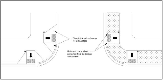
Advisory R304.2.3 Flared Sides. The flared sides are part of the pedestrian circulation path, but are not part of the pedestrian access route. Curb ramps whose sides have returned curbs provide useful directional cues where they are aligned with the pedestrian street crossing and are protected from cross travel by landscaping, street furniture, chains, fencing, or railings.
R304.3 Parallel Curb Ramps
Parallel curb ramps shall comply with R304.3 and R304.5.
R304.3.1 Turning Space
A turning space 1.2 m (4.0 ft) minimum by 1.2 m (4.0 ft) minimum shall be provided at the bottom of the curb ramp and shall be permitted to overlap other turning spaces and clear spaces. If the turning space is constrained on 2 or more sides, the turning space shall be 1.2 m (4.0 ft) minimum by 1.5 m (5.0 ft). The 1.5 m (5.0 ft) dimension shall be provided in the direction of the pedestrian street crossing.
R304.3.2 Running Slope
The running slope of the curb ramp shall be in-line with the direction of sidewalk travel. The running slope of the curb ramp shall be 5 percent minimum and 8.3 percent maximum but shall not require the ramp length to exceed 4.5 m (15.0 ft) minimum. The running slope of the turning space shall be 2 percent maximum.
R304.4 Blended Transitions
Blended transitions shall comply with R304.4 and R304.5.
R304.4.1 Running Slope
The running slope of blended transitions shall be 5 percent maximum.
R304.5 Common Requirements
Curb ramps and blended transitions shall comply with R304.5.
R304.5.1 Width
The width of curb ramps and blended transitions shall comply with 304.5.1.1 or 304.5.1.2, as applicable. If provided, flared sides of curb ramp runs and blended transitions shall be located outside the width of the curb ramp run or blended transition.
R304.5.1.1 Pedestrian Circulation Paths Other Than Shared Use Paths
In pedestrian circulation paths other than shared use paths, the clear width of curb ramp runs, blended transitions, and turning spaces shall be 1.2 m (4.0 ft) minimum.
R304.5.1.2 Shared Use Paths
In shared use paths, the width of curb ramp runs and blended transitions shall be equal to the width of the shared use path.
R304.5.2 Grade Breaks
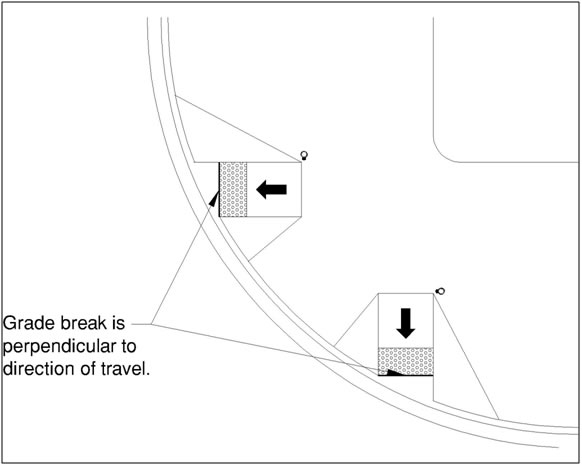
Grade breaks at the top and bottom of curb ramp runs shall be perpendicular to the direction of the ramp run. Grade breaks shall not be permitted on the surface of ramp runs and turning spaces. Surface slopes that meet at grade breaks shall be flush.
R304.5.3 Cross Slope
The cross slope of curb ramps, blended transitions, and turning spaces shall be 2 percent maximum. At pedestrian street crossings without yield or stop control and at midblock pedestrian street crossings, the cross slope shall be permitted to equal the street or highway grade.
Advisory R304.5.3 Cross Slope. Pedestrian street crossings without yield or stop control are crossings where there is no yield or stop sign, or where there is a traffic signal that is designed for the green phase. At pedestrian street crossings without yield or stop control, vehicles can proceed through the intersection without slowing or stopping.
R304.5.4 Counter Slope
The counter slope of the gutter or street at the foot of curb ramp runs, blended transitions, and turning spaces shall be 5 percent maximum.
R304.5.5 Clear Space
Beyond the bottom grade break, a clear space 1.2 m (4.0 ft) minimum by 1.2 m (4.0 ft) minimum shall be provided within the width of the pedestrian street crossing and wholly outside the parallel vehicle travel lane.
R305 Detectable Warning Surfaces
R305.1 General
Detectable warning surfaces shall consist of truncated domes aligned in a square or radial grid pattern and shall comply with R305.
Advisory R305.1 Dome Size. Where the truncated domes are arrayed radially, they may differ in diameter and center-to-center spacing within the ranges specified in R305.1.1 and R305.1.2.
R305.1.1 Dome Size
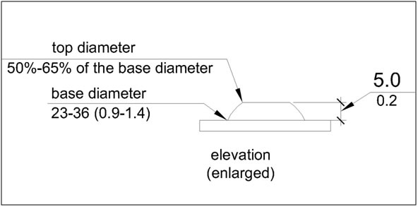
The truncated domes shall have a base diameter of 23 mm (0.9 in) minimum and 36 mm (1.4 in) maximum, a top diameter of 50 percent of the base diameter minimum and 65 percent of the base diameter maximum, and a height of 5 mm (0.2 in).
R305.1.2 Dome Spacing
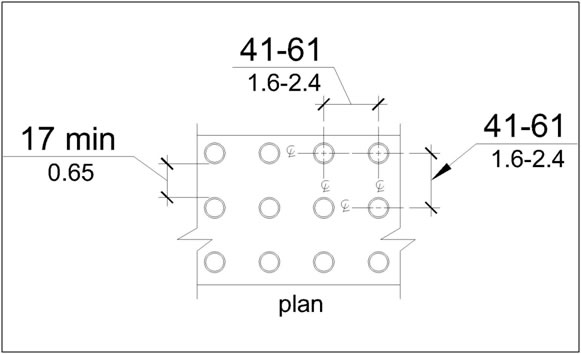
The truncated domes shall have a center-to-center spacing of 41 mm (1.6 in) minimum and 61 mm (2.4 in) maximum, and a base-to-base spacing of 17 mm (0.65 in) minimum, measured between the most adjacent domes.
R305.1.3 Contrast
Detectable warning surfaces shall contrast visually with adjacent gutter, street or highway, or pedestrian access route surface, either light-on-dark or dark-on-light.
Advisory R305.1.3 Contrast. Visual contrast may be provided on the full surface of the curb ramp but should not extend to flared sides. Visual contrast also helps pedestrians who use wheelchairs to locate the curb ramp from the other side of the street.
R305.1.4 Size
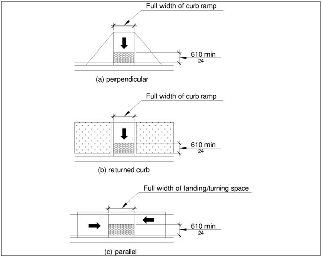
Detectable warning surfaces shall extend 610 mm (2.0 ft) minimum in the direction of pedestrian travel. At curb ramps and blended transitions, detectable warning surfaces shall extend the full width of the ramp run (excluding any flared sides), blended transition, or turning space. At pedestrian at-grade rail crossings not located within a street or highway, detectable warnings shall extend the full width of the crossing. At boarding platforms for buses and rail vehicles, detectable warning surfaces shall extend the full length of the public use areas of the platform. At boarding and alighting areas at sidewalk or street level transit stops for rail vehicles, detectable warning surfaces shall extend the full length of the transit stop.
R305.2 Placement
The placement of detectable warning surfaces shall comply with R305.2.
Advisory R305.2 Placement. Some detectable warning products require a concrete border for proper installation. The concrete border should not exceed 51 mm (2 in). Where the back of curb edge is tooled to provide a radius, the border dimension should be measured from the end of the radius.
R305.2.1 Perpendicular Curb Ramps
On perpendicular curb ramps, detectable warning surfaces shall be placed as follows:
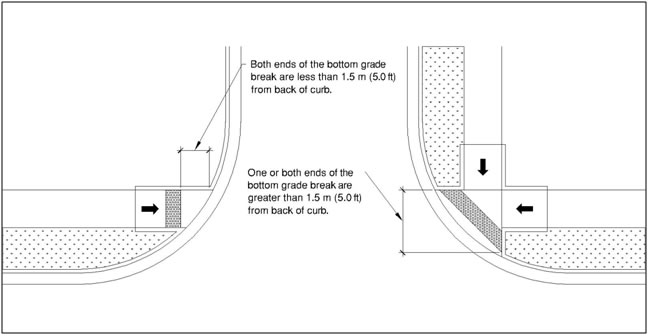
- Where the ends of the bottom grade break are in front of the back of curb, detectable warning surfaces shall be placed at the back of curb.
- Where the ends of the bottom grade break are behind the back of curb and the distance from either end of the bottom grade brake to the back of curb is 1.5 m (5.0 ft) or less, detectable warning surfaces shall be placed on the ramp run within one dome spacing of the bottom grade break.
- Where the ends of the bottom grade break are behind the back of curb and the distance from either end of the bottom grade brake to the back of curb is more than 1.5 m (5.0 ft), detectable warning surfaces shall be placed on the lower landing at the back of curb.
Advisory R305.2.1 Perpendicular Curb Ramps. Detectable warning surfaces are intended to provide a tactile equivalent underfoot of the visible curb line. If detectable warning surfaces are placed too far from the curb line because of a large curb radius, the location may compromise effective crossing. Detectable warning surfaces should not be placed on paving or expansion joints. The rows of truncated domes in detectable warning surfaces should be aligned perpendicular to the grade break between the ramp run and the street so pedestrians who use wheelchairs can “track” between the domes. Where detectable warning surfaces are provided on a surface with a slope that is less than 5 percent, dome orientation is less critical.
R305.2.2 Parallel Curb Ramps
On parallel curb ramps, detectable warning surfaces shall be placed on the turning space at the flush transition between the street and sidewalk.
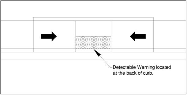
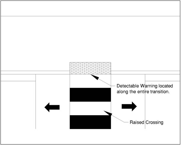
R305.2.3 Blended Transitions
On blended transitions, detectable warning surfaces shall be placed at the back of curb. Where raised pedestrian street crossings, depressed corners, or other level pedestrian street crossings are provided, detectable warning surfaces shall be placed at the flush transition between the street and the sidewalk.
R305.2.4 Pedestrian Refuge Islands
At cut-through pedestrian refuge islands, detectable warning surfaces shall be placed at the edges of the pedestrian island and shall be separated by a 610 mm (2.0 ft) minimum length of surface without detectable warnings.
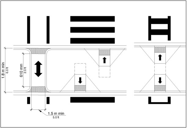
Advisory R305.2.4 Pedestrian Refuge Islands. The edges of cut-through pedestrian refuge islands can provide useful cues to the direction of the crossing.
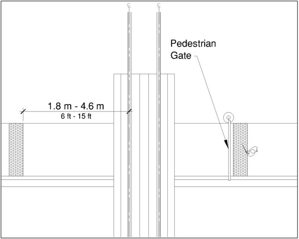
R305.2.5 Pedestrian At-Grade Rail Crossings
At pedestrian at-grade rail crossings not located within a street or highway, detectable warning surfaces shall be placed on each side of the rail crossing. The edge of the detectable warning surface nearest the rail crossing shall be 1.8 m (6.0 ft) minimum and 4.6 m (15.0 ft) maximum from the centerline of the nearest rail. Where pedestrian gates are provided, detectable warning surfaces shall be placed on the side of the gates opposite the rail.
R305.2.6 Boarding Platforms
At boarding platforms for buses and rail vehicles, detectable warning surfaces shall be placed at the boarding edge of the platform.
R305.2.7 Boarding and Alighting Areas
At boarding and alighting areas at sidewalk or street level transit stops for rail vehicles, detectable warning surfaces shall be placed at the side of the boarding and alighting area facing the rail vehicles.
R306 Pedestrian Street Crossings
R306.1 General
Pedestrian street crossings shall comply with R306.
R306.2 Pedestrian Signal Phase Timing
All pedestrian signal phase timing shall comply with section 4E.06 of the MUTCD (incorporated by reference, see R104.2 and shall be based on a pedestrian clearance time that is calculated using a pedestrian walking speed of 1.1 m/s (3.5 ft/s) or less.
R306.3 Roundabouts
Where pedestrian facilities are provided at roundabouts, they shall comply with R306.3.
Advisory R306.3 Roundabouts. Pedestrian street crossings at roundabouts can be difficult for pedestrians who are blind or have low vision to identify because the crossings are located off to the side of the pedestrian circulation path around the street or highway. The continuous traffic flow at roundabouts removes many of the audible cues that pedestrians who are blind use to navigate pedestrian street crossings. Water fountains and other features that produce background noise should not be placed in the middle island of a roundabout because pedestrians who are blind use auditory cues to help detect gaps in traffic. Multi-lane pedestrian street crossings at roundabouts involve an increased risk of pedestrian exposure to accident.
R306.3.1 Separation
Where sidewalks are flush against the curb and pedestrian street crossing is not intended, a continuous and detectable edge treatment shall be provided along the street side of the sidewalk. Detectable warning surfaces shall not be used for edge treatment. Where chains, fencing, or railings are used for edge treatment, they shall have a bottom edge 380 mm (15 in) maximum above the sidewalk.
Advisory R306.3.1 Separation. Carefully delineated pedestrian street crossing approaches with plantings or other defined edges provide effective non-visual cues for identifying pedestrian street crossings at roundabouts. European and Australian roundabouts provide a 610 mm (24 inch) width of tactile surface treatment from the centerline of the curb ramp or blended transition across the full width of the sidewalk to provide an underfoot cue for identifying pedestrian street crossings. Detectable warning surfaces should not be used to guide pedestrians who are blind or have low vision to pedestrian street crossings because detectable warning surfaces indicate the flush transition between the sidewalk and the street or highway. Schemes that remove cyclists from the street or highway by means of a ramp that angles from the curb lane to the sidewalk and then provide re-entry by means of a similar ramp beyond pedestrian street crossings can provide false cues to pedestrians who are using the edge of the sidewalk for wayfinding about the location of pedestrian street crossings.
R306.3.2 Pedestrian Activated Signals
At roundabouts with multi-lane pedestrian street crossings, a pedestrian activated signal complying with R209 shall be provided for each multi-lane segment of each pedestrian street crossing, including the splitter island. Signals shall clearly identify which pedestrian street crossing segment the signal serves.
Advisory R306.3.2 Pedestrian Activated Signals. Roundabouts with single-lane approach and exit legs are not required to provide pedestrian activated signals. Pedestrian activated signals must comply with the requirements for accessible pedestrian signals and pedestrian pushbuttons (see R209). Pedestrian activated signals installed at splitter islands should be carefully located and separated so that signal spillover does not give conflicting information about which pedestrian street crossing has the WALK indication displayed. Pedestrian Hybrid Beacons can be used at roundabouts (see MUTCD sections 4F.01 through 4F.03). Pedestrian Hybrid Beacons are traffic signals that consist of a yellow signal centered below two horizontally aligned red signals. The signals are normally not illuminated. The signals are initiated only upon pedestrian activation and can be timed to minimize the interruption of traffic. The signals cease operation after the pedestrian clears the crosswalk. When activated by a pedestrian, the following signals are displayed to drivers: a flashing yellow signal, then a steady yellow signal, then two steady red signals during the pedestrian walk interval, and then alternating flashing red signals during the pedestrian clearance interval. The following signals are displayed to pedestrians: a steady upraised hand (symbolizing DON’T WALK) when the flashing or steady yellow signal is operating, then a walking person (symbolizing WALK) when the steady red signals are operating, and then a flashing upraised hand (symbolizing DON’T WALK) when the alternating flashing red signals are operating.
R306.4 Channelized Turn Lanes at Roundabouts
At roundabouts with pedestrian street crossings, pedestrian activated signals complying with R209 shall be provided at pedestrian street crossings at multi-lane channelized turn lanes.
R306.5 Channelized Turn Lanes at Other Signalized Intersections
At signalized intersections other than roundabouts with pedestrian street crossings, pedestrian activated signals complying with R209 shall be provided at pedestrian street crossings at multi-lane channelized turn lanes.
R307 Accessible Pedestrian Signals and Pedestrian Pushbuttons
(See R209)
R308 Transit Stops and Transit Shelters
R308.1 Transit Stops
Transit stops shall comply with R308.1.
Advisory R308.1 Transit Stops. Transit stops should be located so that there is a level and stable surface for boarding vehicles. Locating transit stops at signalized intersections increases the usability for pedestrians with disabilities. Where security bollards are installed at transit stops, they must not obstruct the clear space at boarding and alighting areas or reduce the required clear width at pedestrian access routes (see R210).
R308.1.1 Boarding and Alighting Areas
Boarding and alighting areas at sidewalk or street level transit stops shall comply with R308.1.1 and R308.1.3. Where transit stops serve vehicles with more than one car, boarding and alighting areas serving each car shall comply with R308.1.1 and R308.1.3.
Advisory R308.1.1 Boarding and Alighting Areas. Where a transit shelter is provided, the boarding and alighting area can be located either within or outside of the shelter.
R308.1.1.1 Dimensions
Boarding and alighting areas shall provide a clear length of 2.4 m (8.0 ft) minimum, measured perpendicular to the curb or street or highway edge, and a clear width of 1.5 m (5.0 ft) minimum, measured parallel to the street or highway.
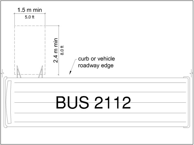
R308.1.1.2 Grade
Parallel to the street or highway, the grade of boarding and alighting areas shall be the same as the street or highway, to the extent practicable. Perpendicular to the street or highway, the grade of boarding and alighting areas shall not be steeper than 2 percent.
R308.1.2 Boarding Platforms
Boarding platforms at transit stops shall comply with R308.1.2 and R308.1.3.
R308.1.2.1 Platform and Vehicle Floor Coordination
Boarding platforms shall be positioned to coordinate with vehicles in accordance with the applicable requirements in 49 CFR parts 37 and 38.
Advisory R308.1.2.1 Platform and Vehicle Floor Coordination. The Department of Transportation regulations (49 CFR parts 37 and 38) require the height of the vehicle floor and the station platform to be coordinated so as to minimize the vertical and horizontal gaps.
R308.1.2.2 Slope
Boarding platforms shall not exceed a slope of 2 percent in any direction. Where boarding platforms serve vehicles operating on existing track or existing street or highway, the slope of the platform parallel to the track or the street or highway is permitted to be equal to the grade of the track or street or highway.
R308.1.3 Common Requirements
Boarding and alighting areas and boarding platforms shall comply with R308.1.3.
R308.1.3.1 Surfaces
The surfaces of boarding and alighting areas and boarding platforms shall comply with R302.7.
Advisory R308.1.3.1 Surfaces. Detectable warning surfaces are required at boarding and alighting areas for rail vehicles and at boarding platforms for buses and rail vehicles (see R208).
R308.1.3.2 Connection
Boarding and alighting areas and boarding platforms shall be connected to streets, sidewalks, or pedestrian circulation paths by pedestrian access routes complying with R302.
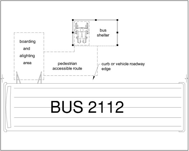
R308.2 Transit Shelters
Transit shelters shall be connected by pedestrian access routes complying with R302 to boarding and alighting areas or boarding platforms complying with R308.1. Transit shelters shall provide a minimum clear space complying with R404 entirely within the shelter. Where seating is provided within transit shelters, the clear space shall be located either at one end of a seat or shall not overlap the area within 460 mm (1.5 ft) from the front edge of the seat. Environmental controls within transit shelters shall be proximity-actuated. Protruding objects within transit shelters shall comply with R402.
Advisory R308.2 Transit Shelters. The clear space must be located entirely within the transit shelter and not interfere with other persons using the seating.
R309 On-Street Parking Spaces
R309.1 General
On-street parking spaces shall comply with R309.
Advisory R309.1 General. R214 specifies how many accessible parking spaces must be provided on the block perimeter where on-street parking is marked or metered. Accessible parking spaces must be identified by signs displaying the International Symbol of Accessibility (see R211.3 and R411). Accessible parking spaces should be located where the street has the least crown and grade and close to key destinations.
R309.2 Parallel Parking Spaces
Parallel parking spaces shall comply with R309.2.
Advisory R309.2 Parallel Parking Spaces. The sidewalk adjacent to accessible parallel parking spaces should be free of signs, street furniture, and other obstructions to permit deployment of a van side-lift or ramp or the vehicle occupant to transfer to a wheelchair or scooter. Accessible parallel parking spaces located at the end of the block face are usable by vans that have rear lifts and cars that have scooter platforms.
R309.2.1 Wide Sidewalks
Where the width of the adjacent sidewalk or available right-of-way exceeds 4.3 m (14.0 ft), an access aisle 1.5 m (5.0 ft) wide minimum shall be provided at street level the full length of the parking space and shall connect to a pedestrian access route. The access aisle shall comply with R302.7 and shall not encroach on the vehicular travel lane.
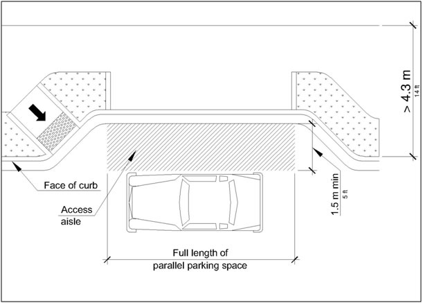
Advisory R309.2.1 Wide Sidewalks. Vehicles may park at the curb or at the parking lane boundary and use the space required by R309.2.1 on either the driver or passenger side of the vehicle to serve as the access aisle.
R309.2.1.1 Alterations
In alterations where the street or sidewalk adjacent to the parking spaces is not altered, an access aisle shall not be required provided the parking spaces are located at the end of the block face.
R309.2.2 Narrow Sidewalks
An access aisle is not required where the width of the adjacent sidewalk or the available right-of-way is less than or equal to 4.3 m (14.0 ft). When an access aisle is not provided, the parking spaces shall be located at the end of the block face.
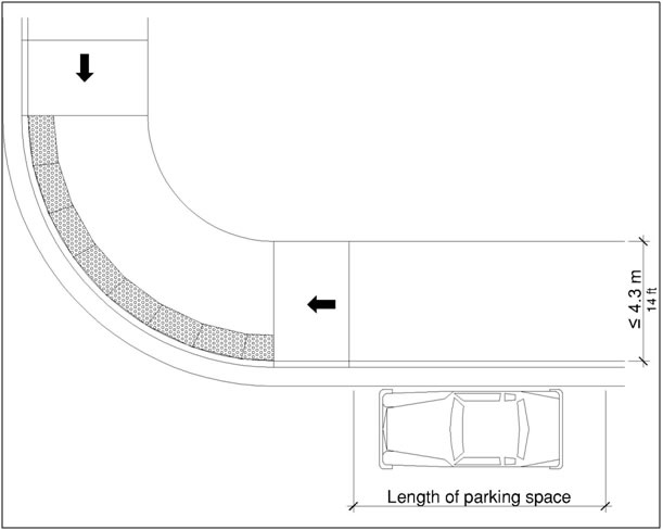
Advisory R309.2.2 Narrow Sidewalks. Vehicle lifts or ramps can be deployed on a 2.4 m (8.0 ft) sidewalk if there are no obstructions.
R309.3 Perpendicular or Angled Parking Spaces
Where perpendicular or angled parking is provided, an access aisle 2.4 m (8.0 ft) wide minimum shall be provided at street level the full length of the parking space and shall connect to a pedestrian access route. The access aisle shall comply with R302.7 and shall be marked so as to discourage parking in the access aisle. Two parking spaces are permitted to share a common access aisle.
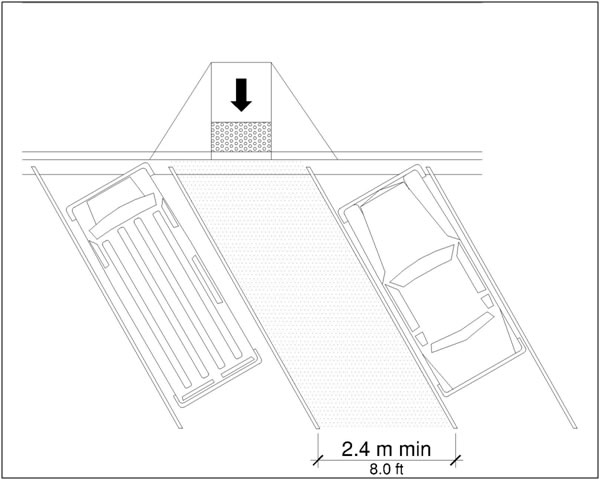
Advisory R309.3 Perpendicular or Angled Parking Spaces. Perpendicular and angled parking spaces permit the deployment of a van side-lift or ramp.
R309.4 Curb Ramps or Blended Transitions
Curb ramps or blended transitions complying with R304 shall connect the access aisle to the pedestrian access route. Curb ramps shall not be located within the access aisle.
Advisory R309.4 Curb Ramps or Blended Transitions. At parallel parking spaces, curb ramps and blended transitions should be located so that a van side-lift or ramp can be deployed to the sidewalk and the vehicle occupant can transfer to a wheelchair or scooter. Parking spaces at the end of the block face can be served by curb ramps or blended transitions at the pedestrian street crossing. Detectable warning surfaces are not required on curb ramps and blended transitions that connect the access aisle to the sidewalk, including where the sidewalk is at the same level as the parking spaces, unless the curb ramps and blended transitions also serve pedestrian street crossings (see R208).
R309.5 Parking Meters and Parking Pay Stations
Parking meters and parking pay stations that serve accessible parking spaces shall comply with R309.5. Operable parts shall comply with R403.
R309.5.1 Location
At accessible parallel parking spaces, parking meters shall be located at the head or foot of the parking space.
Advisory R309.5.1 Location. Locating parking meters at the head or foot of the parking space permits deployment of a van side-lift or ramp or the vehicle occupant to transfer to a wheelchair or scooter.
R309.5.2 Displays and Information
Displays and information shall be visible from a point located 1.0 m (3.3 ft) maximum above the center of the clear space in front of the parking meter or parking pay station.
R310 Passenger Loading Zones
R310.1 General
Passenger loading zones shall comply with R310.
Advisory R310.1 General. Accessible passenger loading zones must be identified by signs displaying the International Symbol of Accessibility (see R211.3 and R411).
R310.2 Vehicle Pull-Up Space
Passenger loading zones shall provide a vehicular pull-up space 2.4 m (8.0 ft) wide minimum and 6.1 m (20.0 ft) long minimum.
R310.3 Access Aisle
Passenger loading zones shall provide access aisles complying with R310.3 adjacent to the vehicle pull-up space. Access aisles shall be at the same level as the vehicle pull-up space they serve and shall not overlap the vehicular travel lane. Curb ramps or blended transitions complying with R304 shall connect the access aisle to the pedestrian access route. Curb ramps are not permitted within the access aisle.
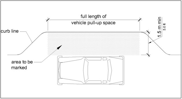
R310.3.1 Width
Access aisles serving vehicle pull-up spaces shall be 1.5 m (5.0 ft) wide minimum.
R310.3.2 Length
Access aisles shall extend the full length of the vehicle pull-up spaces they serve.
R310.3.3 Marking
Access aisles shall be marked so as to discourage parking in them.
R310.3.4 Surfaces
Access aisle surfaces shall comply with R302.7.
