R401 General
R401.1 Scope
The supplemental technical requirements in Chapter 4 shall apply where required by Chapter 2 or where referenced by a requirement in this document.
R402 Protruding Objects
R402.1 General
Protruding objects shall comply with R402.
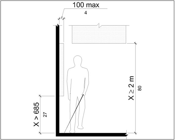
R402.2 Protrusion Limits
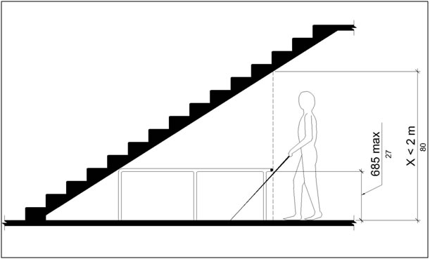
Objects with leading edges more than 685 mm (2.25 ft) and not more than 2 m (6.7 ft) above the finish surface shall protrude 100 mm (4 in) maximum horizontally into pedestrian circulation paths.
R402.3 Post-Mounted Objects
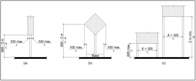
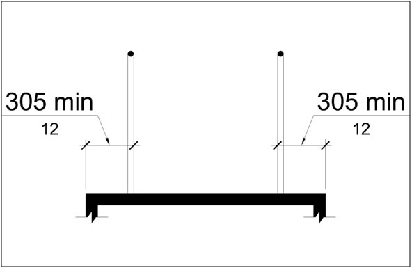
Where objects are mounted on free-standing posts or pylons and the objects are 685 mm (2.25 ft) minimum and 2030 mm (6.7 ft) maximum above the finish surface, the objects shall overhang pedestrian circulation paths 100 mm (4 in) maximum measured horizontally from the post or pylon base. The base dimension shall be 64 mm (2.5 in) thick minimum. Where objects are mounted between posts or pylons and the clear distance between the posts or pylons is greater than 305 mm (1.0 ft), the lowest edge of the object shall be 685 mm (2.25 ft) maximum or 2 m (6.7 ft) minimum above the finish surface.
R402.4 Reduced Vertical Clearance
Guardrails or other barriers to pedestrian travel shall be provided where the vertical clearance is less than 2 m (6.7 ft) high. The leading edge of the guardrail or barrier shall be located 685 mm (2.25 ft) maximum above the finish surface.
R403 Operable Parts
R403.1 General
Operable parts shall comply with R403.
Advisory R403.1 General. Operable parts on accessible pedestrian signals and pedestrian pushbuttons (see R209) and parking meters and parking pay stations that serve accessible parking spaces (see R309.5) must comply with R403.
R403.2 Clear Space
A clear space complying with R404 shall be provided at operable parts.
R403.3 Height
Operable parts shall be placed within one or more of the reach ranges specified in R406.
R403.4 Operation
Operable parts shall be operable with one hand and shall not require tight grasping, pinching, or twisting of the wrist. The force required to activate operable parts shall be 22 N (5 lbs) maximum.
R404 Clear Spaces
R404.1 General
Clear spaces shall comply with R404.
Advisory R404.1 General. Clear spaces are required at operable parts (see R403.2), including accessible pedestrian signals and pedestrian pushbuttons (see R209) and parking meters and parking pay stations that serve accessible parking spaces (see R309.5). Clear spaces are also required at benches (see R212.6) and within transit shelters (see R308.2).
R404.2 Surfaces
Surfaces of clear spaces shall comply with R302.7 and shall have a running slope consistent with the grade of the adjacent pedestrian access route and cross slope of 2 percent maximum.
R404.3 Size
Clear spaces shall be 760 mm (2.5 ft) minimum by 1220 mm (4.0 ft) minimum.
R404.4 Knee and Toe Clearance
Unless otherwise specified, clear spaces shall be permitted to include knee and toe clearance complying with R405.
R404.5 Position
Unless otherwise specified, clear spaces shall be positioned for either forward or parallel approach to an element.
R404.6 Approach
One full unobstructed side of a clear space shall adjoin a pedestrian access route or adjoin another clear space.
R404.7 Maneuvering Space
Where a clear space is confined on all or part of three sides, additional maneuvering space shall be provided in accordance with R404.7.1 and R404.7.2.
R404.7.1 Forward Approach
The clear space and additional maneuvering space shall be 915 mm (3.0 ft) wide minimum where the depth exceeds 610 mm (2.0 ft).
R404.7.2 Parallel Approach
The clear space and additional maneuvering space shall be 1525 mm (5.0 ft) wide minimum where the depth exceeds 380 mm (1.25 ft).
R405 Knee and Toe Clearance
R405.1 General
Where space beneath an element is included as part of a clear space, the space shall comply with R405. Additional space shall not be prohibited beneath an element but shall not be considered as part of the clear space.
Advisory R405.1 General. Clearances are measured in relation to the usable clear space, not necessarily to the vertical support for an element. When determining clearance under an object, care should be taken to ensure that the space is clear of any obstructions.
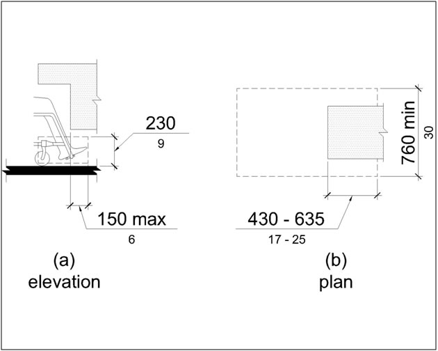
R405.2 Toe Clearance
R405.2.1 General
Space under an element between the finish surface and 230 mm (9 in) above the finish surface shall be considered toe clearance and shall comply with R405.2.
R405.2.2 Maximum Depth
Toe clearance shall extend 635 mm (2.1 ft) maximum under an element.
R405.2.3 Minimum Required Depth
Where toe clearance is required at an element as part of a clear space, the toe clearance shall extend 430 mm (1.4 ft) minimum under the element.
R405.2.4 Width
Toe clearance shall be 760 mm (2.5 ft) wide minimum.
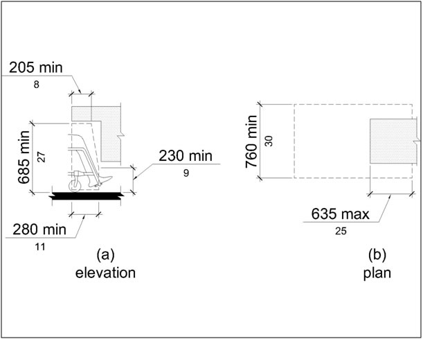
R405.3 Knee Clearance
R405.3.1 General
Space under an element between 230 mm (9 in) and 685 mm (2.25 ft) above the finish surface shall be considered knee clearance and shall comply with R405.3.
R405.3.2 Maximum Depth
Knee clearance shall extend 635 mm (2.1 ft) maximum under an element at 230 mm (9 in) above the finish surface.
R405.3.3 Minimum Required Depth
Where knee clearance is required under an element as part of a clear space, the knee clearance shall be 280 mm (11 in) deep minimum at 230 mm (9 in) above the finish surface, and 205 mm (8 in) deep minimum at 685 mm (2.25 ft) above the finish surface.
R405.3.4 Clearance Reduction
Between 230 mm (9 in) and 685 mm (2.25 ft) above the finish surface, the knee clearance shall be permitted to reduce at a rate of 25 mm (1 in) in depth for each 150 mm (6 in) in height.
R405.3.5 Width
Knee clearance shall be 760 mm (2.5 ft) wide minimum.
R406 Reach Ranges
R406.1 General
Reach ranges shall comply with R406.
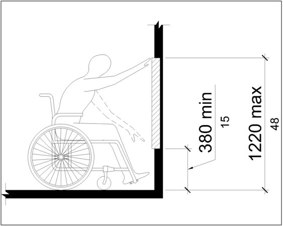
R406.2 Unobstructed Forward Reach
Where a forward reach is unobstructed, the high forward reach shall be 1220 mm (4.0 ft) maximum and the low forward reach shall be 380 mm (1.25 ft) minimum above the finish surface. Forward reach over an obstruction is not permitted.
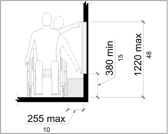
R406.3 Unobstructed Side Reach
Where a clear space allows a parallel approach to an element and the side reach is unobstructed, the high side reach shall be 1220 mm (4.0 ft) maximum and the low side reach shall be 380 mm (1.25 ft) minimum above the finish surface. An obstruction shall be permitted between the clear space and the element where the depth of the obstruction is 255 mm (10 in) maximum.
R407 Ramps
R407.1 General
Ramps shall comply with R407.
R407.2 Running Slope
Ramp runs shall have a running slope between 5 percent minimum and 8.3 percent maximum.
Advisory R407.2 Running Slope. Ramps with the least possible running slope accommodate the widest range of users. Providing stairways along with ramps, where possible, benefits pedestrians with heart disease, limited stamina, and others for whom distance presents a greater barrier than steps.
R407.3 Cross Slope
The cross slope of ramp runs shall be 2 percent maximum.
R407.4 Width
The clear width of a ramp run and, where handrails are provided, the clear width between handrails shall be 915 mm (3.0 ft) minimum.
R407.5 Rise
The rise for any ramp run shall be 760 mm (2.5 ft) maximum.
R407.6 Landings
Ramps shall have landings at the top and the bottom of each ramp run. Landings shall comply with R407.6.
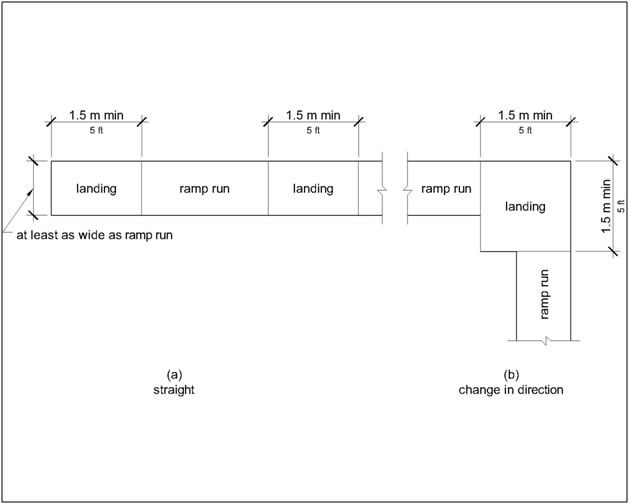
R407.6.1 Slope
Landing slopes shall be 2 percent maximum in any direction.
R407.6.2 Width
The landing clear width shall be at least as wide as the widest ramp run leading to the landing.
R407.6.3 Length
The landing clear length shall be 1.5 m (5.0 ft) long minimum.
R407.6.4 Change in Direction
Ramps that change direction between runs at landings shall have a clear landing 1.5 m (5.0 ft) minimum by 1.5 m (5.0 ft) minimum.
R407.7 Surfaces
Surfaces of ramp runs and landings shall comply with R302.7.
R407.8 Handrails
Ramp runs with a rise greater than 150 mm (6 in) shall have handrails complying with R409.
R407.9 Edge Protection
Edge protection complying with R407.9.1 or R407.9.2 shall be provided on each side of ramp runs and ramp landings.
R407.9.1 Extended Ramp Surface
The surface of the ramp run or landing shall extend 305 mm (1.0 ft) minimum beyond the inside face of a handrail complying with R409.
Advisory R407.9.1 Extended Ramp Surface. The extended surface prevents wheelchair casters and crutch tips from slipping off the ramp surface.
R407.9.2 Curb or Barrier
A curb or barrier shall be provided that prevents the passage of a 100 mm (4 in) diameter sphere, where any portion of the sphere is within 100 mm (4 in) of the finish surface.
R408 Stairways
R408.1 General
Stairways shall comply with R408.
R408.2 Treads and Risers
All steps on a flight of stairs shall have uniform riser heights and uniform tread depths. Risers shall be 100 mm (4 in) high minimum and 180 mm (7 in) high maximum. Treads shall be 280 mm (11 in) deep minimum.
R408.3 Open Risers
Open risers are not permitted.
R408.4 Tread Surface
Stairway treads shall comply with R302.7. Changes in level are not permitted.
R408.5 Nosings
The radius of curvature at the leading edge of the tread shall be 13 mm (0.5 inch) maximum. Nosings that project beyond risers shall have the underside of the leading edge curved or beveled. Risers shall be permitted to slope under the tread at an angle of 30 degrees maximum from vertical. The permitted projection of the nosing shall extend 38 mm (1.5 in) maximum over the tread below.
R408.6 Handrails
Stairways shall have handrails complying with R409.
R409 Handrails
R409.1 General
Handrails required at ramps and stairways, and handrails provided on pedestrian circulation paths shall comply with R409.
Advisory R409.1 General. Handrails are required on ramp runs with a rise greater than 150 mm (6 in) (see R407.8) and stairways (see R408.6). Handrails are not required on pedestrian circulation paths. However, if handrails are provided on pedestrian circulation paths, the handrails must comply with R409 (see R217). The requirements in R409.2, R409.3, and R409.10 apply only to handrails at ramps and stairways, and do not apply to handrails provided on pedestrian circulation paths.
R409.2 Where Required
Handrails shall be provided on both sides of ramps and stairways.
R409.3 Continuity
Handrails shall be continuous within the full length of each ramp run or stair flight. Inside handrails on switchback or dogleg ramps and stairways shall be continuous between ramp runs or stair flights.
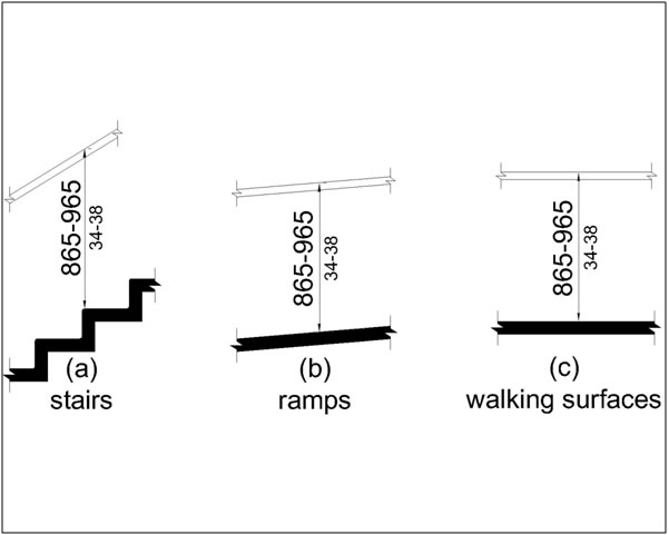
R409.4 Height
Top of gripping surfaces of handrails shall be 865 mm (2.8 ft) minimum and 965 mm (3.2 ft) maximum vertically above walking surfaces, ramp surfaces, and stair nosings. Handrails shall be at a consistent height above walking surfaces, ramp surfaces, and stair nosings.
R409.5 Clearance
Clearance between handrail gripping surfaces and adjacent surfaces shall be 38 mm (1.5 in) minimum.
R409.6 Gripping Surface
Handrail gripping surfaces shall be continuous along their length and shall not be obstructed along their tops or sides. The bottoms of handrail gripping surfaces shall not be obstructed for more than 20 percent of their length. Where provided, horizontal projections shall occur 38 mm (1.5 in) minimum below the bottom of the handrail gripping surface.
Advisory R409.6 Gripping Surface. Pedestrians with disabilities and others benefit from continuous gripping surfaces that permit users to reach the fingers outward or downward to grasp the handrail.
R409.7 Cross Section
Handrail gripping surfaces shall have a cross section complying with R409.7.1 or R409.7.2. Where expansion joints are necessary for large spans of handrails, the expansion joint is permitted to be smaller than the specified cross section diameters for a 25mm (1 in) length.
R409.7.1 Circular Cross Section
Handrail gripping surfaces with a circular cross section shall have an outside diameter of 32 mm (1.25 in) minimum and 51 mm (2 in) maximum.
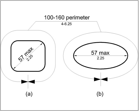
R409.7.2 Non-Circular Cross Sections
Handrail gripping surfaces with a non-circular cross section shall have a perimeter dimension of 100 mm (4 in) minimum and 160 mm (6.25 in) maximum, and a cross-section dimension of 57 mm (2.25 in) maximum.
R409.8 Surfaces
Handrail gripping surfaces and any surfaces adjacent to them shall be free of sharp or abrasive elements and shall have rounded edges.
R409.9 Fittings
Handrails shall not rotate within their fittings. Where expansion joints are necessary for large spans of handrails, the expansion joint is permitted to rotate in its fitting.
R409.10 Handrail Extensions
Handrail gripping surfaces shall extend beyond and in the same direction of ramp runs and stair flights in accordance with R409.10. Extensions shall not be required for continuous handrails at the inside turn of switchback or dogleg ramps and stairways. In alterations where handrail extensions would reduce the clear width required for pedestrian access routes, handrail extensions shall not be required.
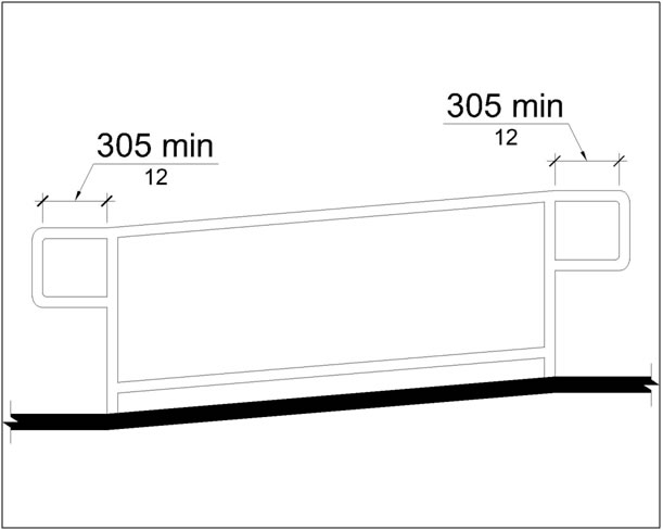
R409.10.1 Top and Bottom Extension at Ramps
Ramp handrails shall extend horizontally above the landing for 305 mm (1.0 ft) minimum beyond the top and bottom of ramp runs. Extensions shall return to a wall, guard, or the landing surface, or shall be continuous to the handrail of an adjacent ramp run.
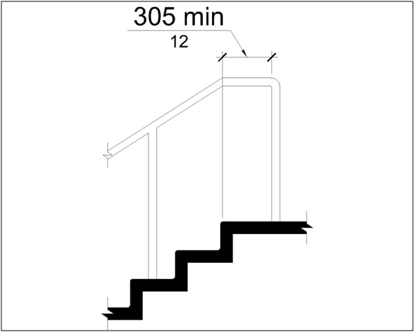
R409.10.2 Top Extension at Stairways
At the top of a stair flight, handrails shall extend horizontally above the landing for 305 mm (1.0 ft) minimum beginning directly above the first riser nosing. Extensions shall return to a wall, guard, or the landing surface, or shall be continuous to the handrail of an adjacent stair flight.
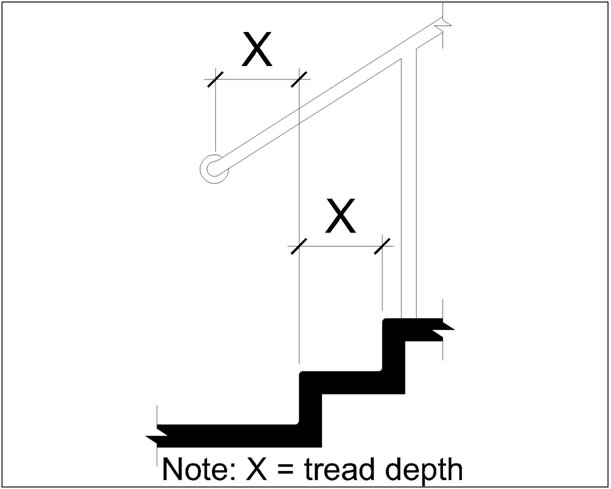
R409.10.3 Bottom Extension at Stairways
At the bottom of a stair flight, handrails shall extend at the slope of the stair flight for a horizontal distance at least equal to one tread depth beyond the last riser nosing. Extensions shall return to a wall, guard, or the landing surface, or shall be continuous to the handrail of an adjacent stair flight.
R410 Visual Characters on Signs
R410.1 General
Visual characters on signs shall comply with R410.
R410.2 Finish and Contrast
Characters and their background shall have a non-glare finish. Characters shall contrast with their background with either light characters on a dark background or dark characters on a light background.
Advisory R410.2.1 Finish and Contrast. Signs are more legible for pedestrians with low vision when characters contrast as much as possible with their background. Additional factors affecting the ease with which the text can be distinguished from its background include shadows cast by lighting sources, surface glare, and the uniformity of the text and its background colors and textures.
R410.3 Case
Characters shall be uppercase or lowercase or a combination of both.
R410.4 Style
Characters shall be conventional in form. Characters shall not be italic, oblique, script, highly decorative, or of other unusual forms.
R410.5 Character Proportions
Characters shall be selected from fonts where the width of the uppercase letter “O” is 55 percent minimum and 110 percent maximum of the height of the uppercase letter “I”.
R410.6 Character Height
Minimum character height shall comply with Table R410.6. Viewing distance shall be measured as the horizontal distance between the character and an obstruction preventing further approach towards the sign. Character height shall be based on the uppercase letter “I”.
Table R410.6 Visual Character Height
| Height to Finish Surface From Baseline of Character | Horizontal Viewing Distance | Minimum Character Height |
| 1.0 m (3.3 ft) to less than or equal to 1.8 m (5.8 ft) | Less than 1.8 m (6.0 ft) | 16 mm (0.625 in) |
| 1.8 m (6.0 ft) and greater | 16 mm (0.625 in), plus 3.2 mm (0.125 in) per 0.3 m (1.0 ft) of viewing distance above 1.8 m (6.0 ft) | |
| Greater than 1.8 m (5.8 ft) to less than or equal to 3.0 m (10.0 ft) | Less than 4.6 m (15.0 ft) | 51 mm (2 in) |
| 4.6 m (15.0 ft) and greater | 51 mm (2 in), plus 3.2 mm (0.125 in) per 0.3 m (1.0 ft) of viewing distance above 4.6 m (15.0 ft) | |
| Greater than 3.0 m (10.0 ft) | Less than 6.4 m (21.0 ft) | 75 mm (3 in) |
| 6.4 m (21.0 ft) and greater | 75 mm (3 in), plus 3.2 mm (0.125 in) per 0.3 m (1.0 ft) of viewing distance above 6.4 m (21.0 ft) |
R410.7 Height from Finish Surface
Visual characters shall be 1.0 m (3.25 ft) minimum above the finish surface.
R410.8 Stroke Thickness
Stroke thickness of the uppercase letter “I” shall be 10 percent minimum and 30 percent maximum of the height of the character.
R410.9 Character Spacing
Character spacing shall be measured between the two closest points of adjacent characters, excluding word spaces. Spacing between individual characters shall be 10 percent minimum and 35 percent maximum of character height.
R410.10 Line Spacing
Spacing between the baselines of separate lines of characters within a message shall be 135 percent minimum and 170 percent maximum of the character height.
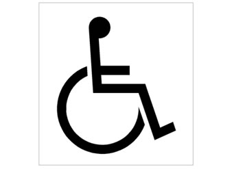
R411 International Symbol of Accessibility
The International Symbol of Accessibility shall comply with Figure R411. The symbol and its background shall have a non-glare finish. The symbol shall contrast with its background with either a light symbol on a dark background or a dark symbol on a light background.